|
by Vladimir Yabukov |
||||||||||||||||||||||||||||||||
| Some of the longest serving battleships in the world, the
Gangut (or as they were known in the Russian navy - Sevastopol) class ships
had eventful careers. They fought in four wars, took part in three revolutions
and outlived all but one of their contemporaries while losing 50% of the
class in the process.
Four battleships of the class (Petropavlovsk, Sevastopol, Gangut and Poltava - named after famous Russian battles) were laid down in June 1909 and at the time were some of the most powerful battleships designed. Unfortunately their long building times meant that by the time they entered service in November 1914 British Queen Elizabeth class battleships were nearing completion, and they were becoming obsolete. They displaced 23,300 tons, had top speed of 24 knots and were armed with twelve powerful 12" guns in four triple turrets. Their guns were the most powerful 12" guns used in WWI with the heaviest shell of any 12" gun before the American Alaska class in 1940s, another distinctive feature of the design was the fact that the guns elevated to 25 degrees where most of their contemporaries only managed 12 to 15 degree elevation. Their most interesting feature was the armor scheme which was uniquely Russian and was a direct consequence of the defeat at Tsushima. At Tsushima Russian ships were turned into burning pyres by the rain of Japanese HE shells hitting their unarmored sides, while even modest armor was not penetrated by them. So as a consequence, the Russian navy theorized that the best way to protect a Battleship is to armor as much of the hull as possible with modest armor, a complete antithesis to the American All-or-Nothing scheme; almost the entire hull was armored, but the main belt was only 225 mm thick. While this was justifiable in the view of the performance of German and British shells at Jutland, later in their careers when AP shells that actually worked appeared they became woefully underarmored. All four ships entered service within two months of each other in November 1914 - January 1915. Throughout WWI they patrolled the minefield positions at the mouth of the Gulf of Finland, only venturing out of the gulf twice, when Petropavlovsk and Gangut covered mine laying operations near Gotland in Oct-Nov 1915. Since they were the only Russian dreadnought type battleships in the Baltic, Russian high command was very reluctant to risk them and they never fired their guns at the enemy in anger during the war. This also led to their bored crews being involved in revolutionary activities. There was a minor mutiny on board two of them in 1915 and their crews took active part in both March and October 1917 Revolutions. All four ships took part in the epic Ice Voyage in March 1918 when the ships of the Russian Navy were withdrawn back to Kronshtadt from their forward bases through the ice covered Gulf of Finland to prevent them from being captured by the advancing Germans. After that due to the start of the Civil War all but one of them (Petropavlovsk) were placed in reserve. In a tragic twist of fate the ships that never fired at the Germans during WWI, were used to fire on fellow Russians and the former allies during the Civil War. First, on 31 May 1919 as one of the few operational ships of the Red Navy in the Baltic Petropavlovsk was covering a reconnaissance of the British forces by Red Navy destroyer Azard, when they were attacked by 8 British destroyers. Petropavlovsk was able to drive them off, but no ships on either side were hit. This, surprisingly, was the only time in their 42 year long careers when any of the Gangut class battleships were involved in the ships to ship action. In June 1919 the garrisons of the two forts on the Southern coast of the Gulf of Finland mutinied against the Soviets and Petropavlovsk was involved in shelling them into submission. In August 1919 the British claimed to have sunk Petropavlovsk in a MTB raid on Kronshtadt. That myth has persisted until the end of the cold war, but in reality the torpedo missed and hit the pier next to the ship. In November 1919 the class suffered its first loss when Poltava, that has been ostensibly placed in reserve, but in reality was all but abandoned pier side, caught fire and burned for over a day and half. The resulting damage was so great that despite that fact that the hull was kept around until after WWII and there were periodic half hearted attempts to repair the ship, it was never operational again. Last time the ships were in action during the Civil War was in March 1921, when they went into action on the anti-government side. In March 1921 the sailors of the Kronshtadt Naval Base mutinied, led mostly by the battleship crews, and declared their intention to start a third revolution. In the ironic change the forts that they helped silence in 1919 now fired on them on the side of the government. Despite heavy fire from the battleships (almost 700 12" rounds were fired by them), the mutiny was crushed in 8 days. The ships were subsequently re-named - Gangut to Oktyabr'skaya Revolutsiya, Sevastopol to Parizhskaya Kommuna, Petropavlovsk to Marat and Poltava to Frunze.. The next several years the ships were mostly in reserve, but starting from 1922-24 they were slowly being repaired and brought back into operational readiness. Several years of routine maneuvers followed as Red Navy was rebuilding itself. In 1929 Parizhskaya Kommuna along with a cruiser Profintern left Baltic for the last time and transited to the Black Sea (the only time the ships of this class visited an ocean). Starting from 1931 until 1938 these three ships were being slowly modernized. Superstructures were build up, boilers replaced and AA guns added. Parizhskaya Kommuna was modernized the most - mid-deck armor was strengthened from 25 mm to 76 mm, gun elevation was increased to 40 degrees, and anti torpedo bulges were added which brought the displacement up to almost 31,000 tons. Baltic ships were also modernized, but to the lesser extent. Baltic ships were active during the Winter War shelling Finnish positions
and coast defense batteries. Two ships fired almost 400 12" rounds at the
Finns during the conflict. All three ships were active in WWII, through
not in the same way as the ships of the other navies - instead of the ocean
operations, they were used a floating batteries due to the nature of the
conflict in the East. In September 1941 both Baltic ships were extremely
active in support of the defenders of Leningrad. Marat alone fired 1042
12" shells in the span of eight days. They also faced some of the heaviest
air strikes faced by any ships during WWII, each sustaining several damaging
but non disabling hits. On 23 September 1941 Marat was hit by two 500 or
1000 kg bombs, which pierced the deck armor and caused the explosion of
the forward 12" magazine. The entire forward third of the ship was destroyed,
326 men died and the ship settled to the bottom of the harbor (which fortunately
was only two meter below the bottom of the ship). Yet amazingly two aft
turrets of the ship remained operational and on October 31 they were back
in action. By mid 1942 the #2 turret was also repaired. Both ships were
active throughout the Blockade and Oktyabr'skaya Revolutsiya was the last
ship of the class to fire its gun in anger when it shelled Finnish positions
on 9 June 1944 (and obtained two direct hits on the concrete strong points
at the distance of 30,000 meters).
|
||||||||||||||||||||||||||||||||
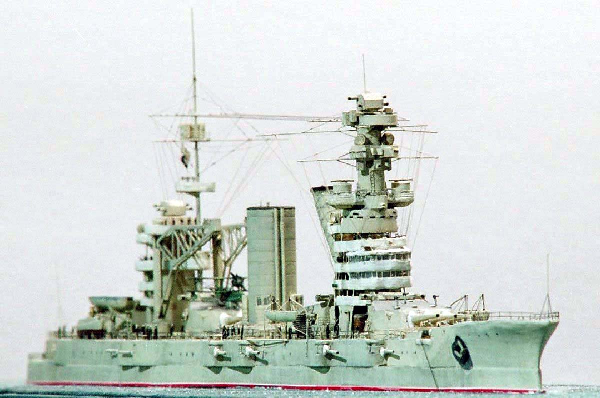
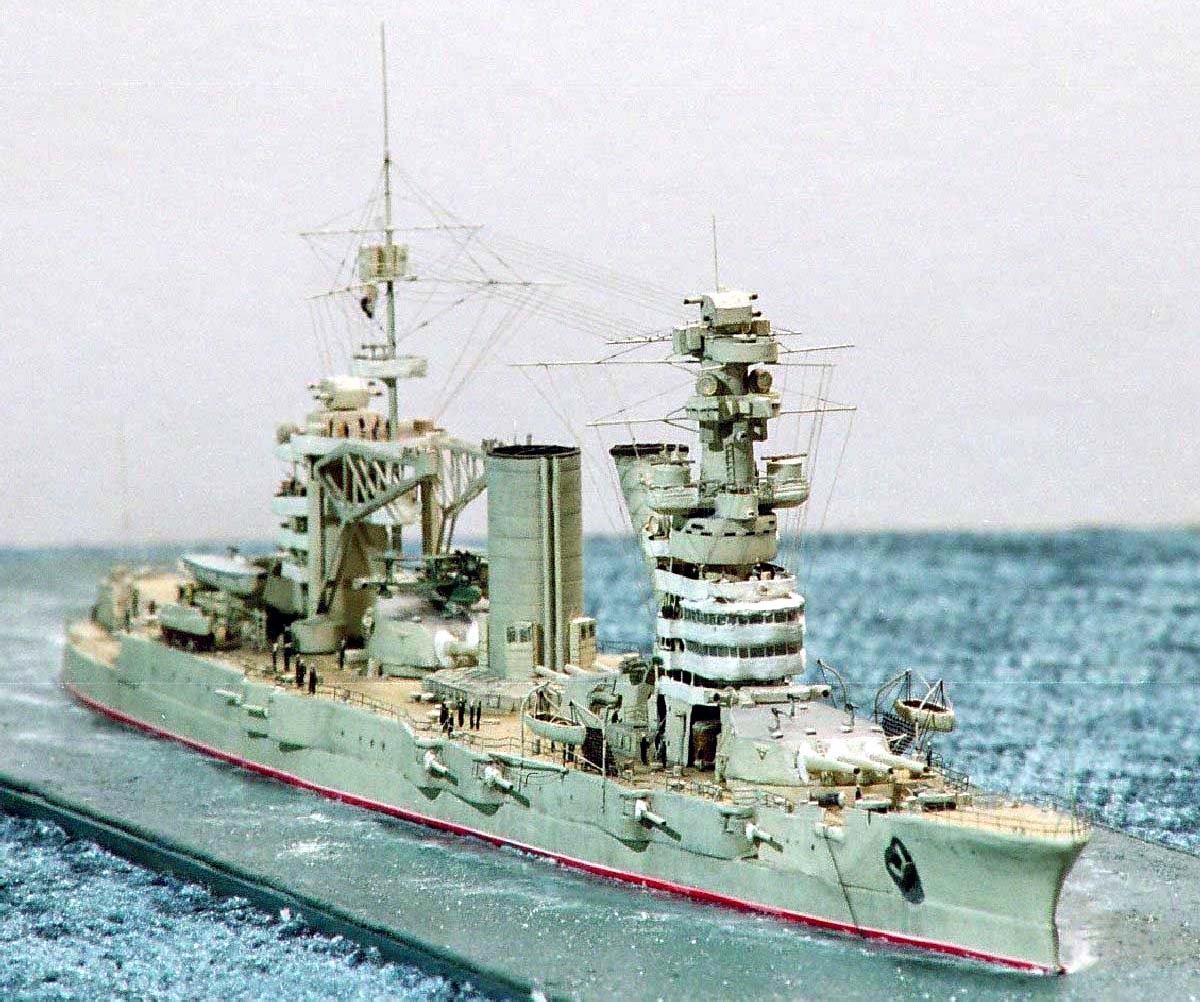
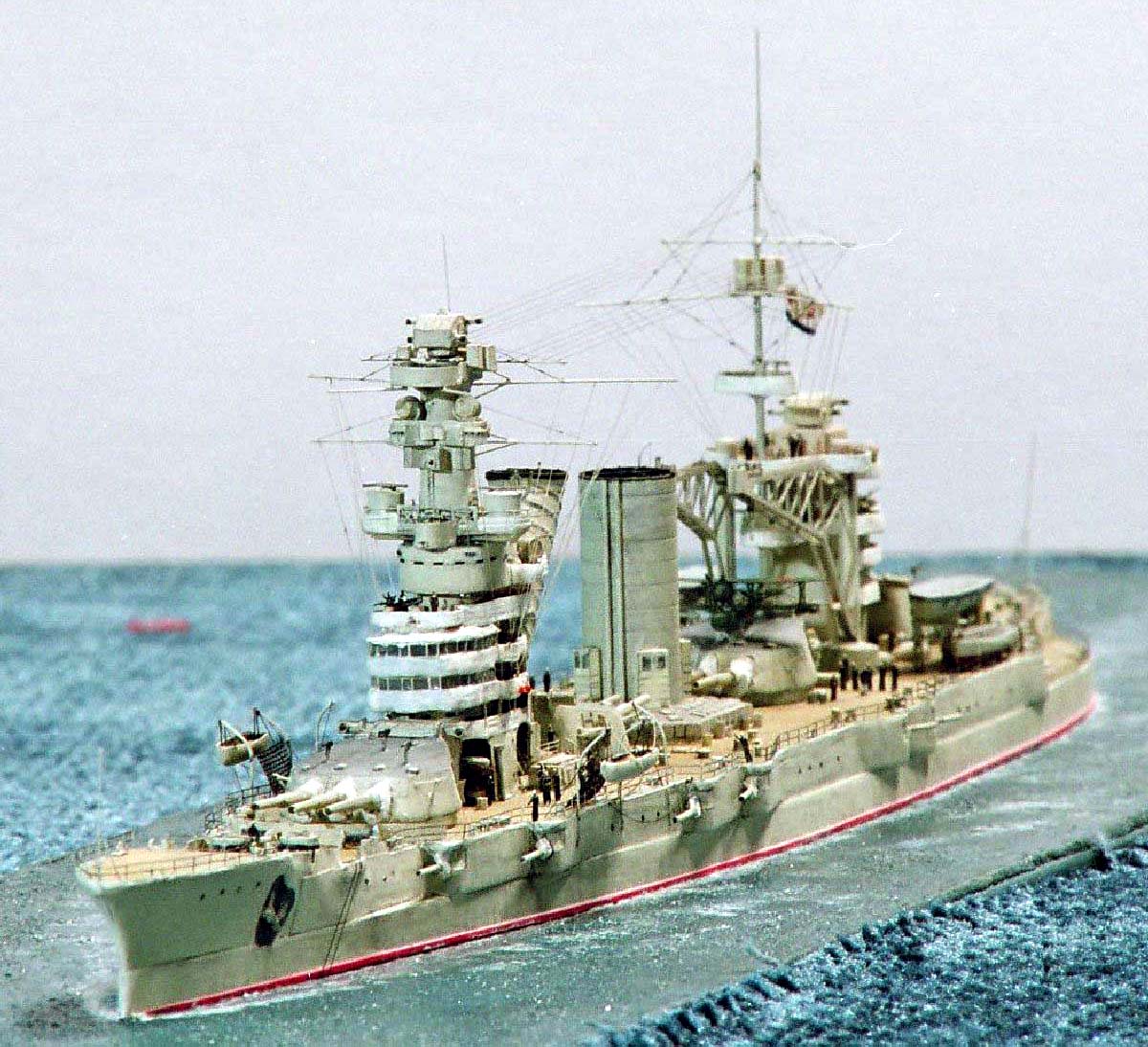
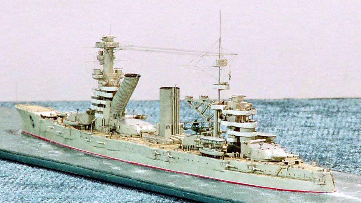
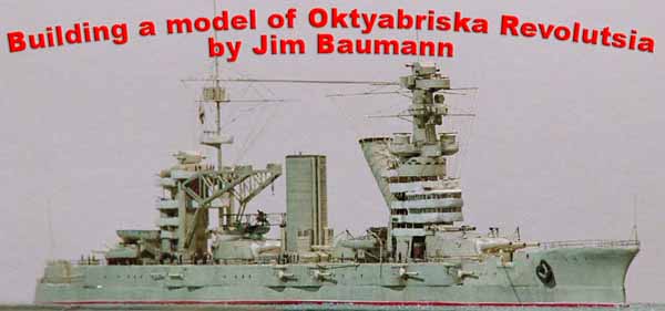
| Building the Model of Oktabriskaya Revolutsiya | ||||||||||||||||||||||||||||||||
|
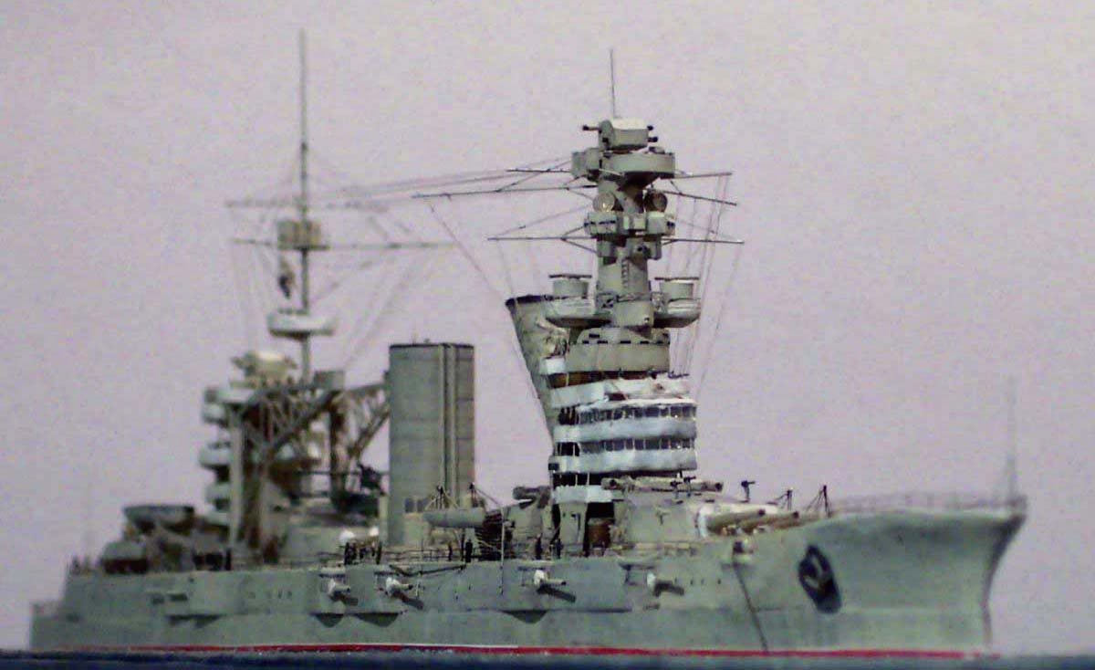
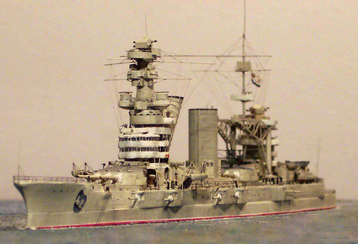
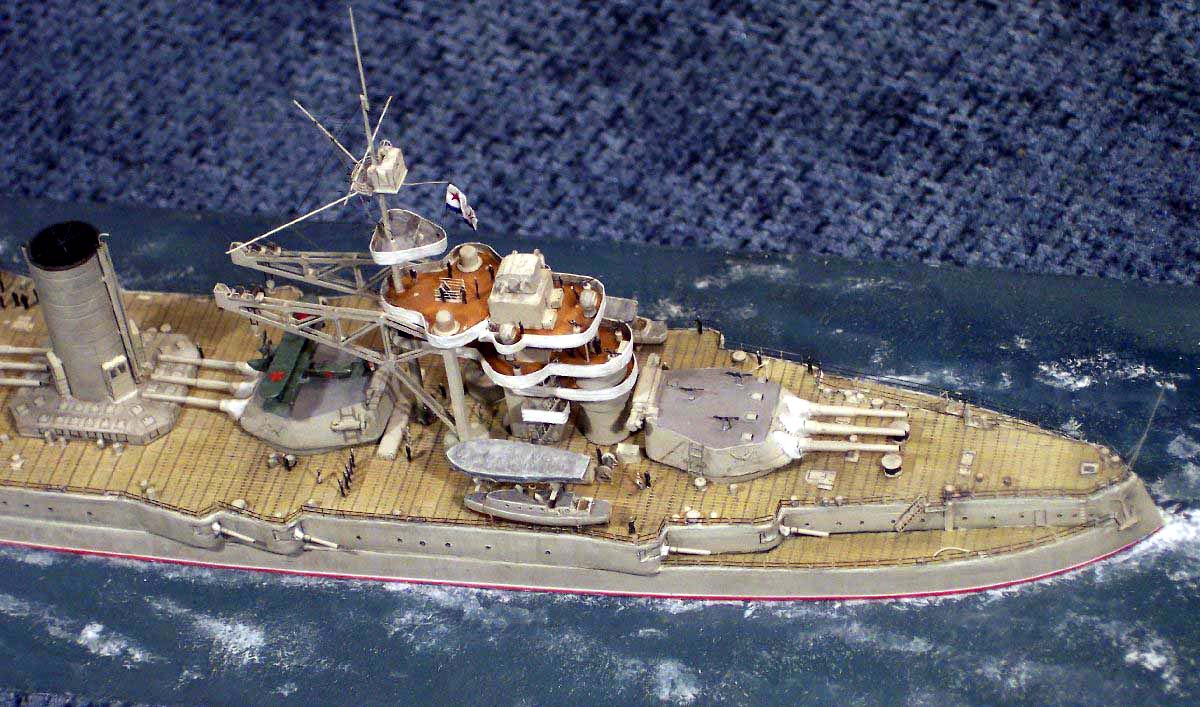
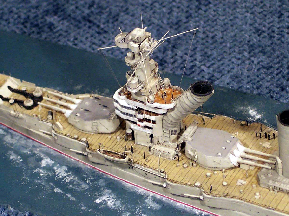
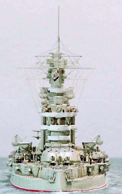
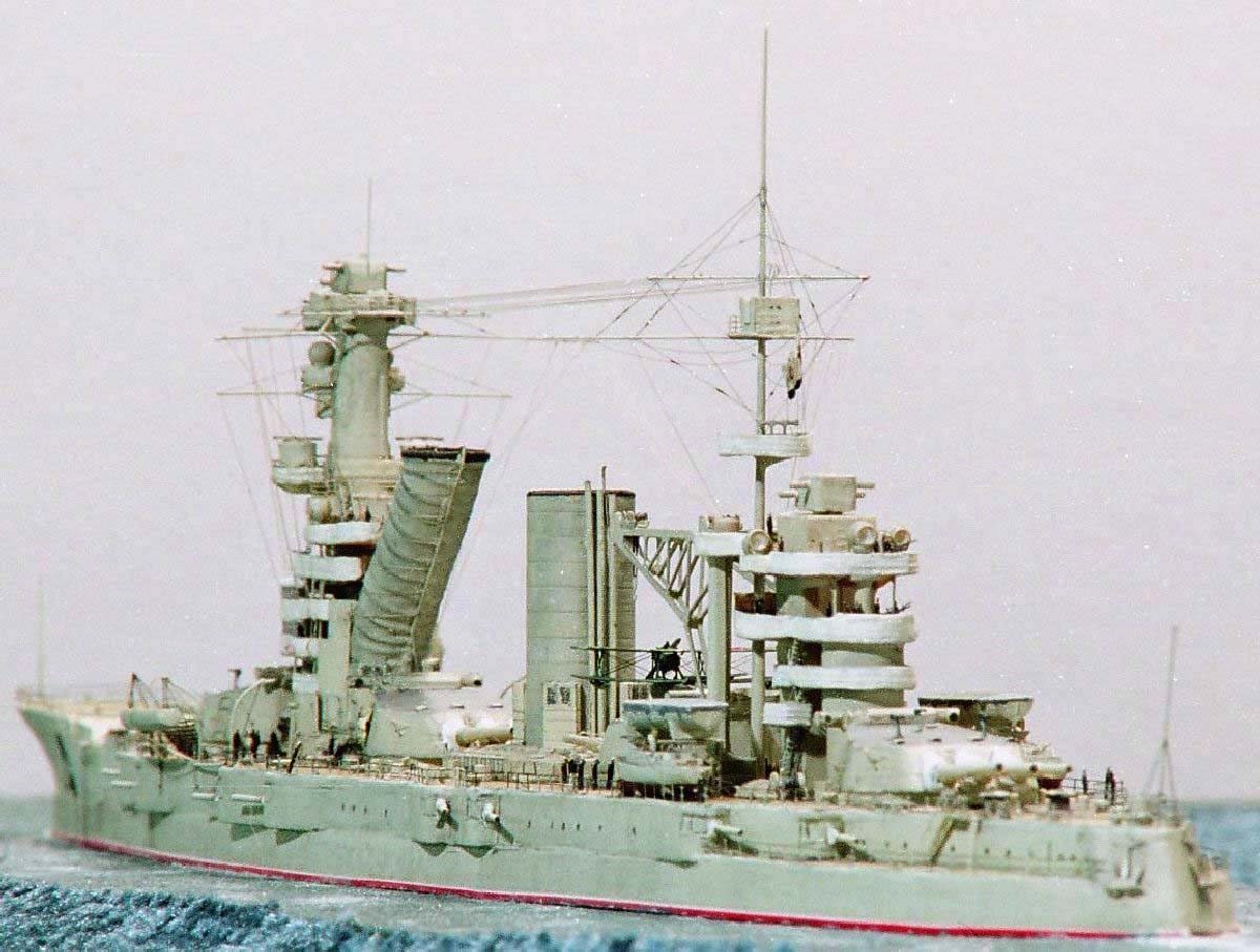
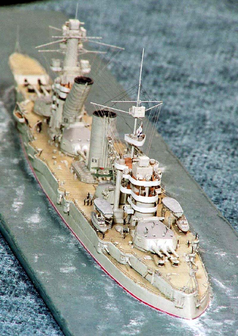
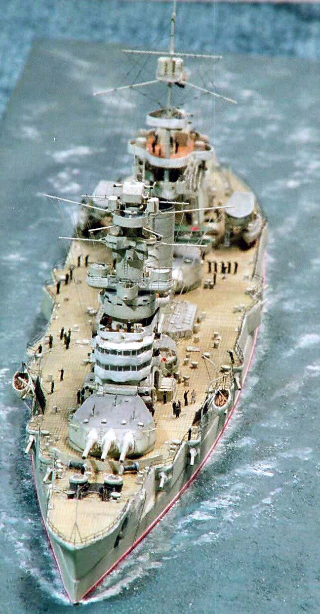
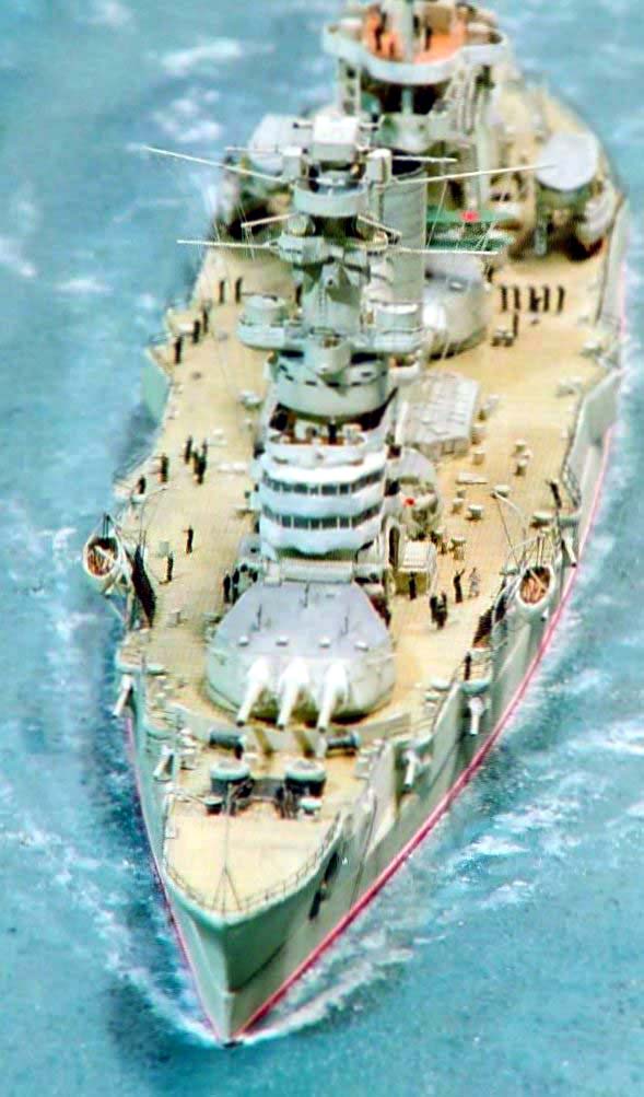
Oktabriskaya Revolutsiya, built in 1914 was originally called Gangut, she languished unused and poorly maintained during the Russian civil war which followed the 1917 Revolution. Re-activated by the Soviet Government in the early 1920's, she was renamed Oktabriskaya Revolutsia (October Revolution) In the early 1930's she underwent an extensive modernization and rebuild. She retained the symmetrical 4 turret layout-- but gained a new flared clipper bow along with a new lofty forward superstructure which required the aft swept funnel with its S-bend to clear smoke from the upper bridge levels. These features coupled with the two enormous boat and aircraft cranes made for a truly unique profile, which is among the most distinctive of any warship ever. She was affectionately named Oktabrina by her crew. |
||||||||||||||||||||||||||||||||
| There are various 1/700 kits available of the Gangut class,
they vary in quality- for the full Gangut kit story click
here.
I acquired this HP kit of the ship unseen off e-bay Germany from fellow modeller Martin Kohring who was thinning out his collection. |
click images
to enlarge |
|||||||||||||||||||||||||||||||
| Once I had the kit in my possession its greatest flaw came to light immediately; the total absence of any kind of deck planking! | ||||||||||||||||||||||||||||||||
| Oktabrina like most ships had her decks laid fore-and-aft
but bisected in the russian shipbuilding manner of the time by metal strips
running athartships. Having inspected the hull casting which is fundamentally
accurate dimensionally. I found the casemates were not sufficiently high
when compared to photos and with this finding I formulated the Oktabrina
kit rescue plan!
After a suitable interval of three years maturing in my kit stash.... .the time was right to tackle this challenging build. |
||||||||||||||||||||||||||||||||
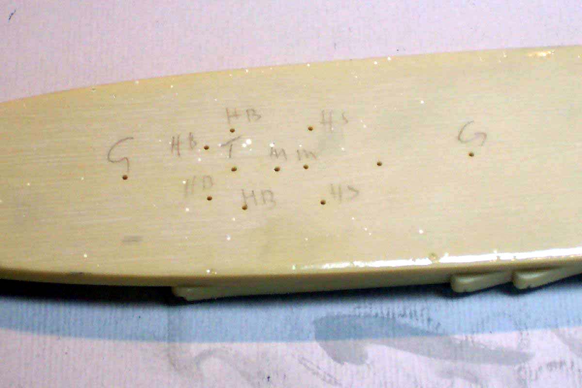
| Having acquired a plethora of reference material to verify/counter
the plentiful deck detail on the hull casting I started to pare it all
away, but only after the centers of all barbettes, vents, masts etc. had
been drilled through the hull and labeled to ensure a reasonable starting
point after the decking was installed.
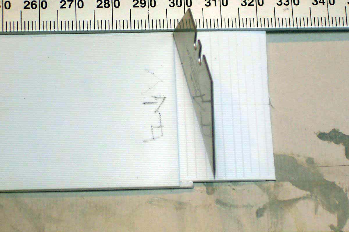
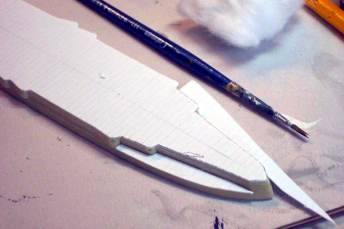
In order to portray the cross planking I made a small sliding jig out of styrene so as to be able to score the Evergreen N-scale car siding across the 'planking'. I was concerned that the athwartships line effect may be too overpowering when painted so elected to score only at 2 mm intervals. |
 |
|||||||||||||||||||||||||||||||
 |
||||||||||||||||||||||||||||||||
| The cross- scored styrene sheet deck was fitted to the now dead flat smooth pared resin deck and cemented using CA gel. | 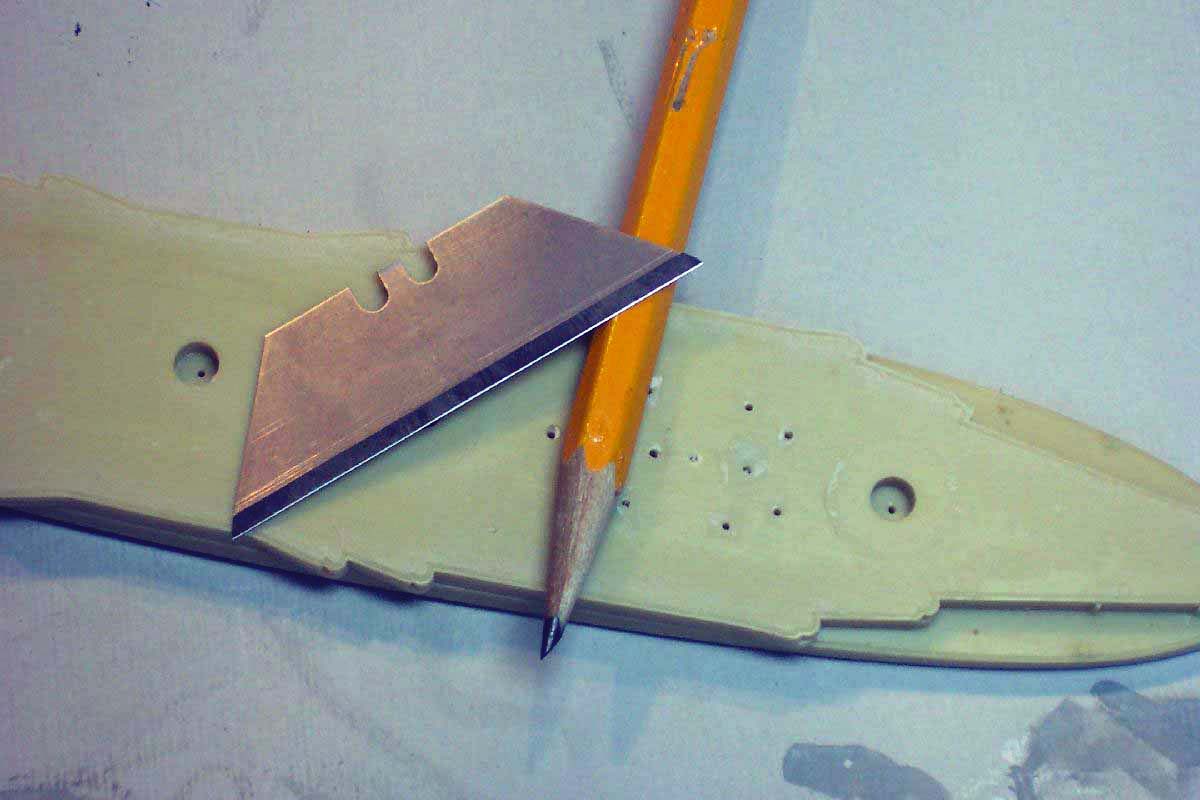 |
|||||||||||||||||||||||||||||||
| It is essential in this type of operation to ensure that a centerline is drawn and adhered to!. With CA you get only 20 seconds wriggle time. Thereafter the edges were trimmed, the lower quarter decks were cut, installed and any small remaining gaps filled. | 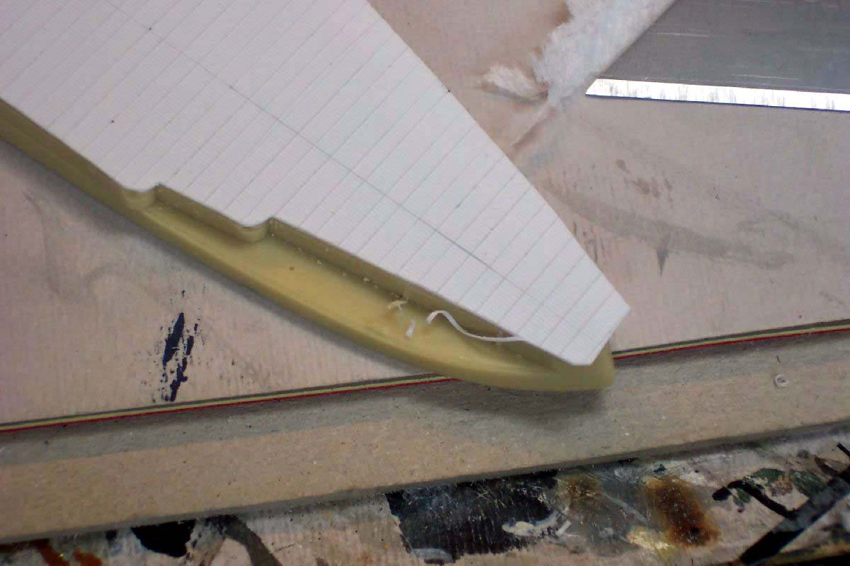 |
|||||||||||||||||||||||||||||||
 |
||||||||||||||||||||||||||||||||
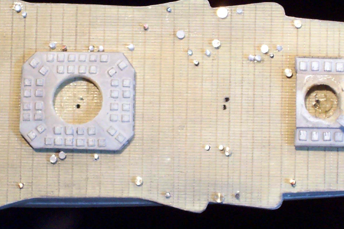
| The center positions of barbettes etc. were re-drilled and construction could begin in earnest. After failed attempts to make perfect circles using styrene square section and the unsuccessful joining of the the two ends... I decided to simplify making the barbettes by wrapping styrene square section around the turret bottoms and gluing bit by bit, Crude but very effective. | 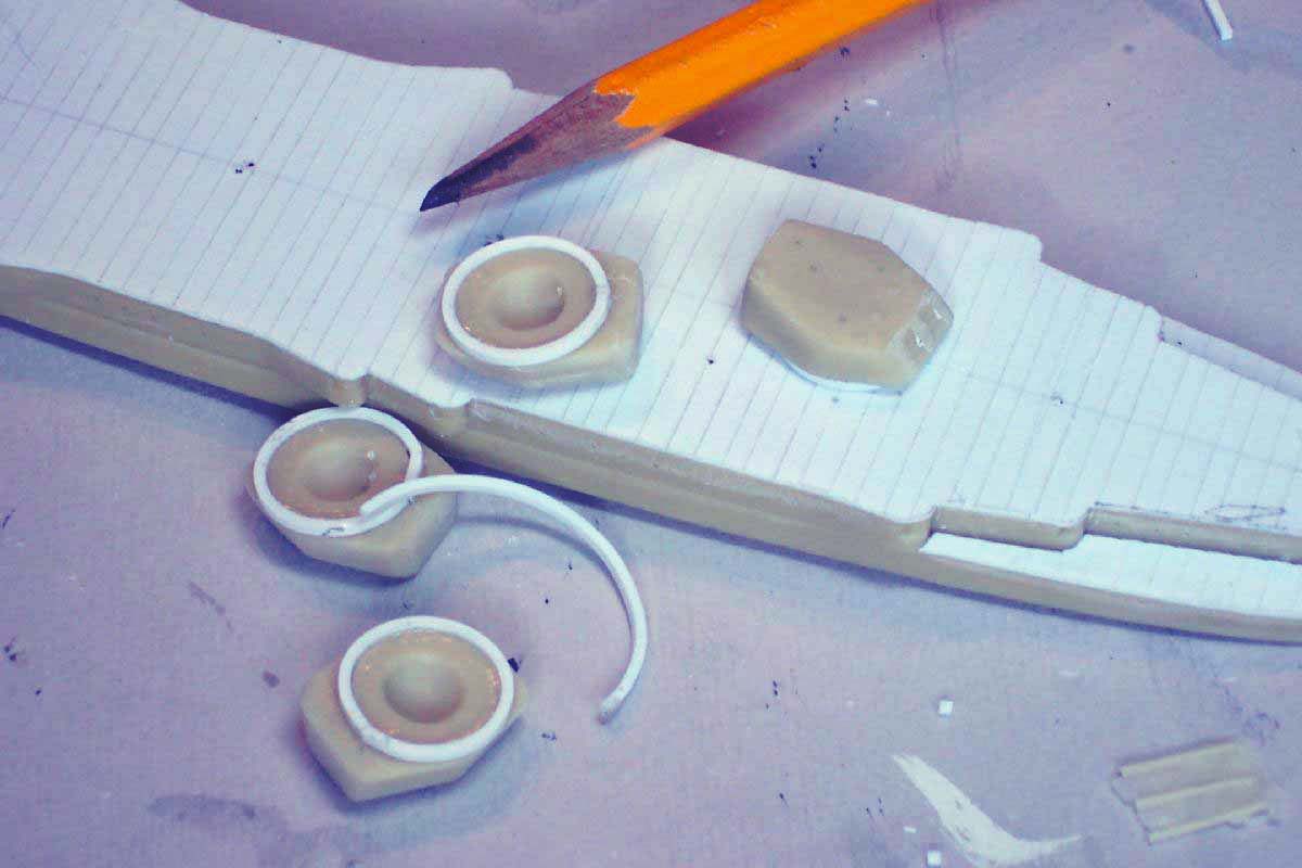 |
|||||||||||||||||||||||||||||||
| The deck was painted and the cross scores were picked up with pencil lead dust applied by brush. | 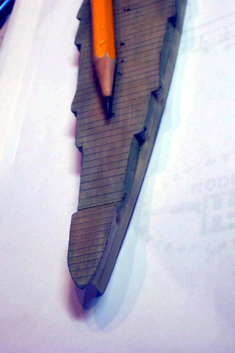 |
|||||||||||||||||||||||||||||||
| On my next russian dreadnought re-decking project I shall
score the deck at 1 mm intervals. The effect was not overpowering at all
indeed now the deck was affixed (permanently!!) I could no longer use my
sliding jig. So resorted to using a ruler and pencil to merely draw in
the additional athwartships lines a lesson learnt!
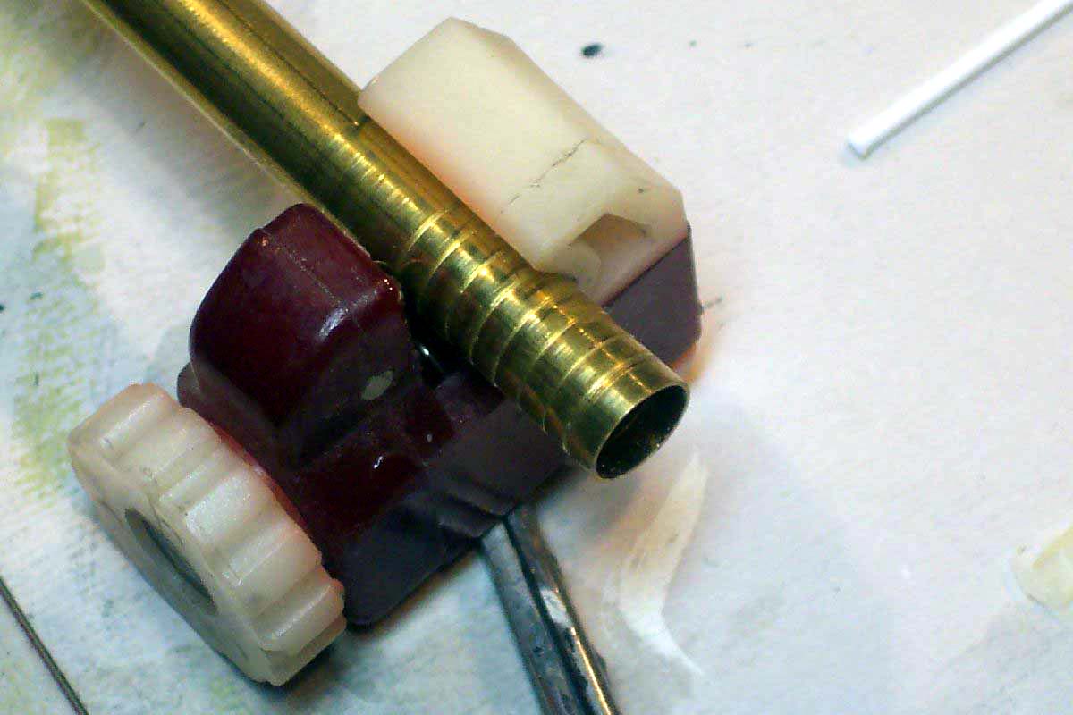
I was unhappy with the kit supplied funnel checking plans and photos it was slightly too thin as well as having a variety of casting blemishes. A replacement was fabricated of brass tubing this being lightly scored to represent the handrails- wrong- but when painted effective in this scale. The steam pipes were made of brass and nicklesilver wire, base vents were styrene block |
 |
|||||||||||||||||||||||||||||||
 |
||||||||||||||||||||||||||||||||
| The fwd stack was actually of the right diameter and outline, merely needing the top to be added to in the form of a sliver of brass tube to complete the S-bend to the correct amount. | 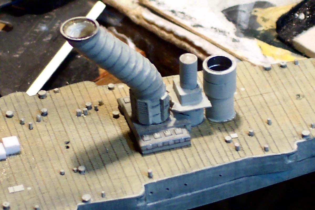 |
|||||||||||||||||||||||||||||||
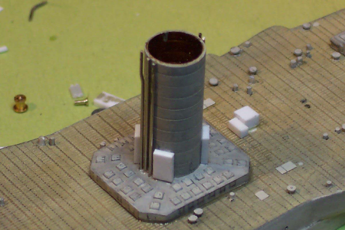
| The armored conning towers previously severed from the hull casting were no longer looking as crisp as I wished so replacements were made of aluminum tubing. The now exaggerated step was reduced to near scale by wrapping with vinyl tape and securing with CA. | ||||||||||||||||||||||||||||||||
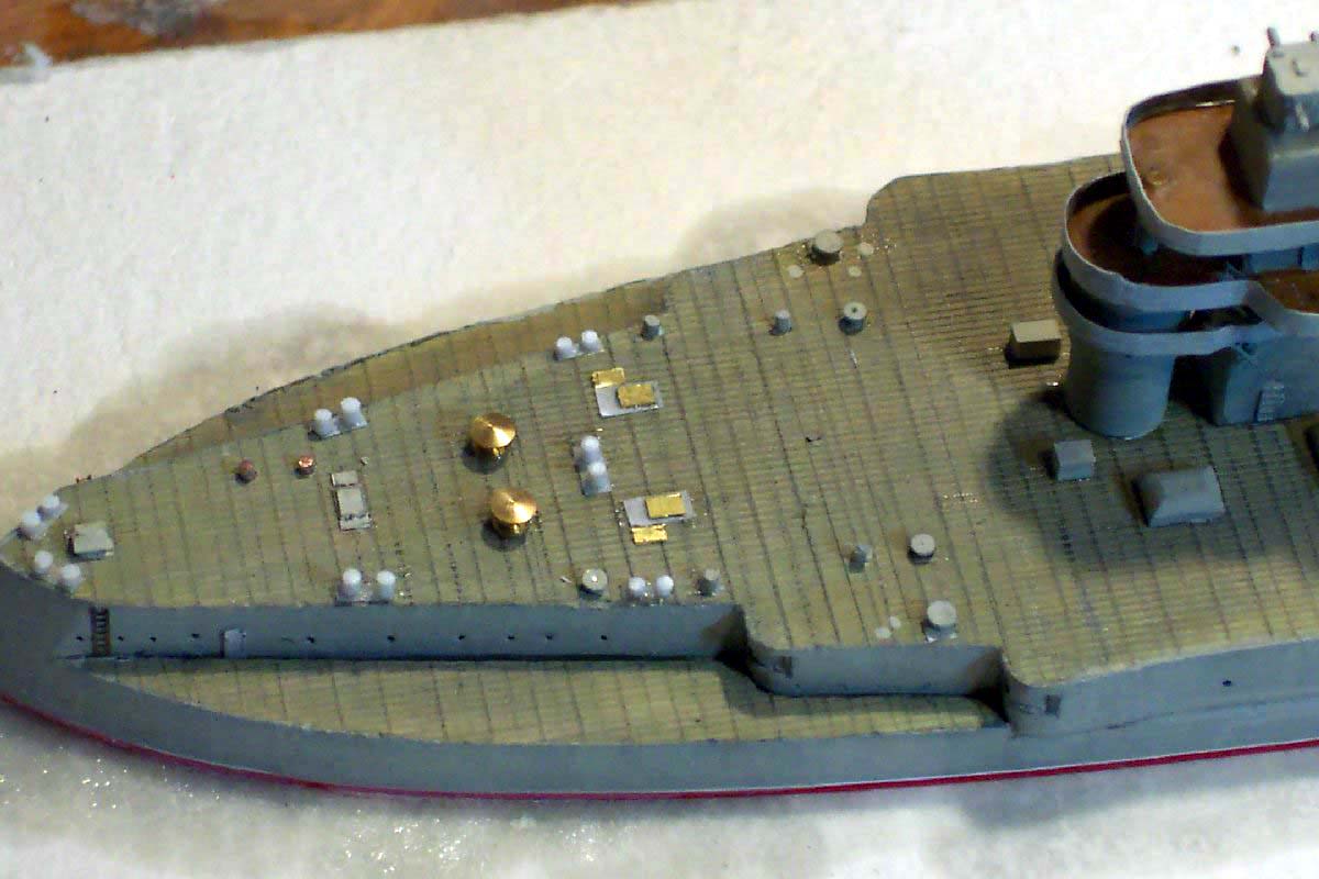
| The fitting of a myriad of vents, coal scuttles, hatches,
and all the 'stuff' that should be on the deck. For siting of these details
I used the plan from the Sevastopol monograph along with the Schwartzer
plan along with the few on deck photos I could locate. The vents were made
of various sizes of model railway rivets, styrene rod, brass rod and stretched
sprue according to whichever matched the appropriate size. All these items
were placed into redrilled holes for secure mounting as well as easier
painting.
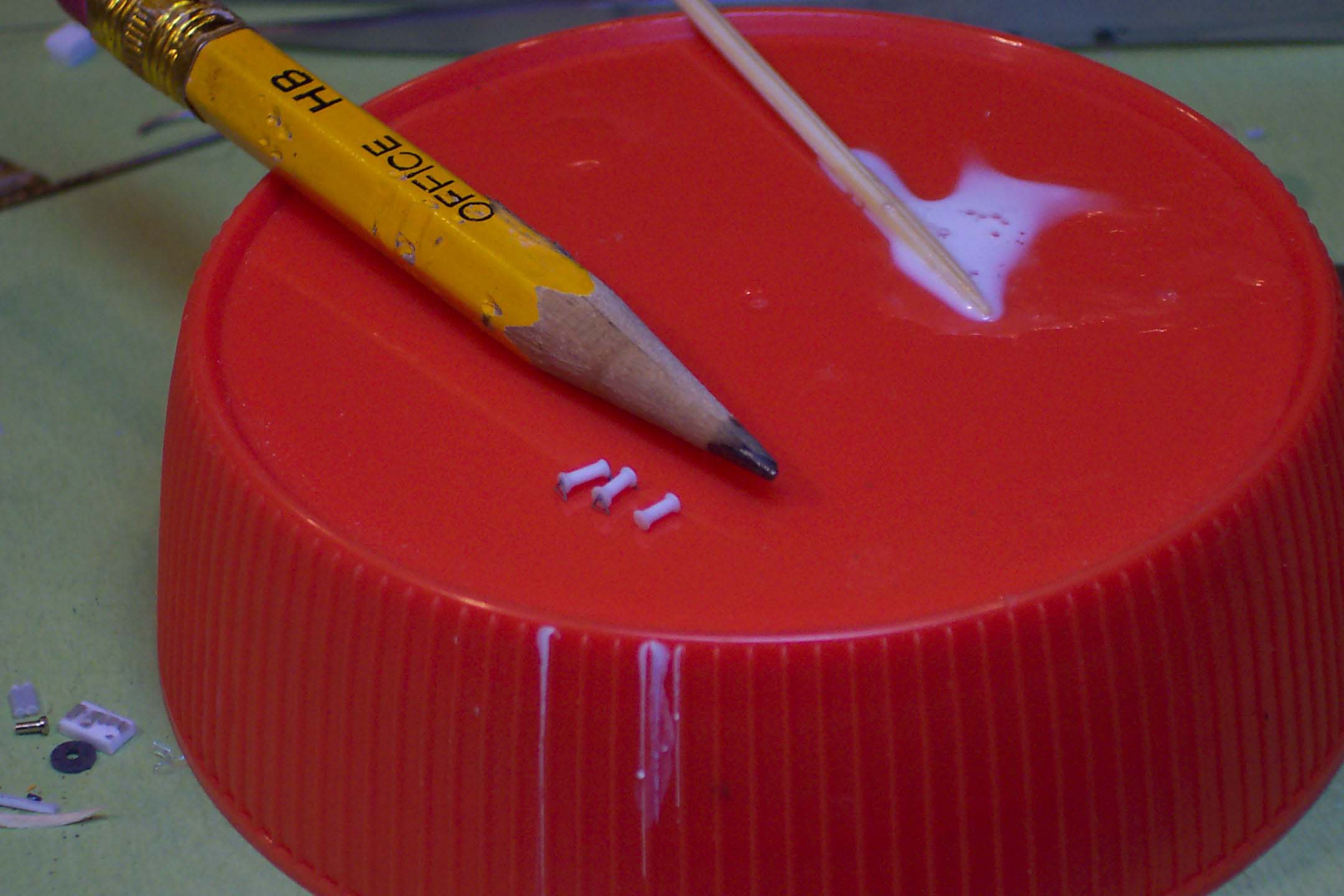
The mooring bits and fairleads were made of a sliver of CA infused paper for super thin bases and styrene rod for the bits |
 |
|||||||||||||||||||||||||||||||
 |
||||||||||||||||||||||||||||||||
 |
||||||||||||||||||||||||||||||||
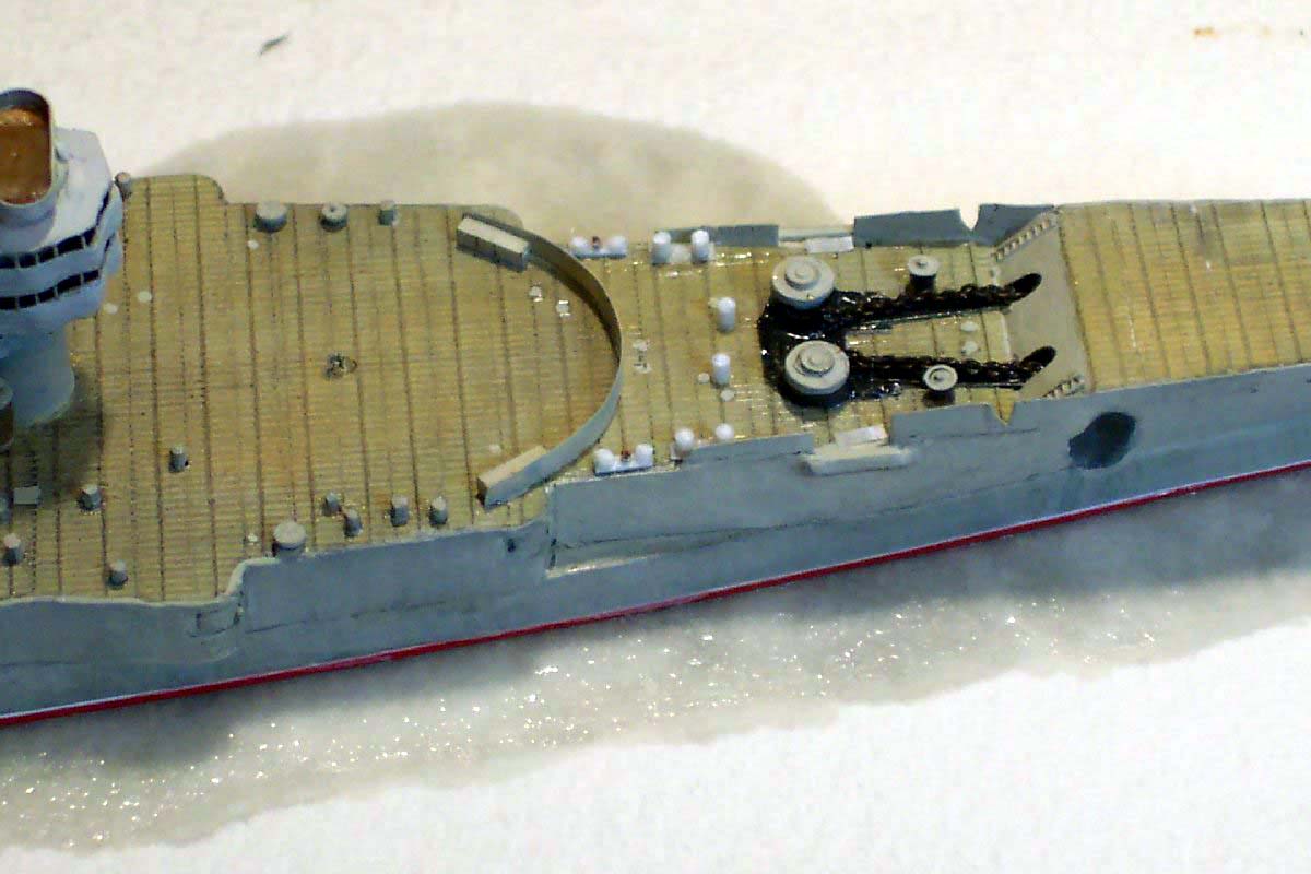
| The forward bulwarks adjacent to the anchor windlasses were made of paper infused with CA, as were the chain ways and the fwd breakwater. The main capstans and windlasses were made of model railway locomotive washout plugs on 4 mm scale( OO/Ho and 2 mm ( N-scale) scale respectively. One should never underestimate the value of a trawl through a well stocked model railway shop, for brass bits as well as alternative PE parts many of which have great 'crossover' value. | 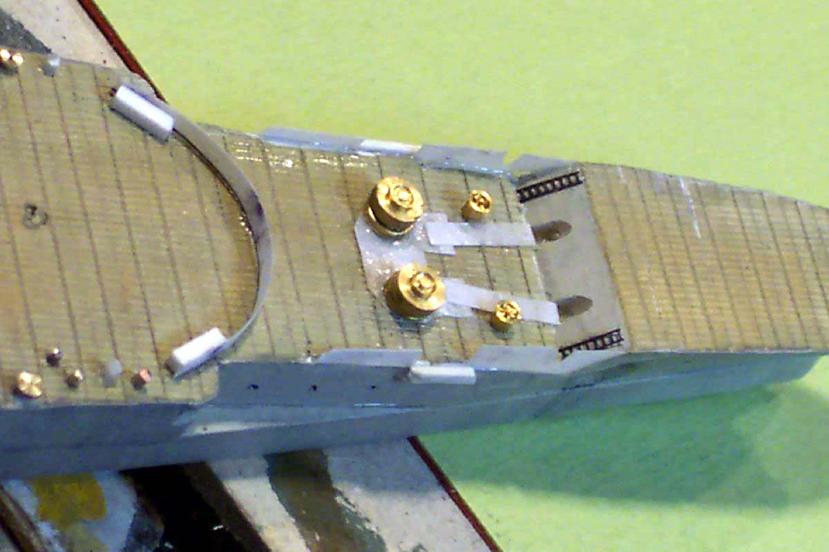 |
|||||||||||||||||||||||||||||||
| The Breakwater supporting gussets were added later using small pieces of stretched sprue then infilled with thinned white glue this saves lots of trial and error with ever decreasing triangles. | 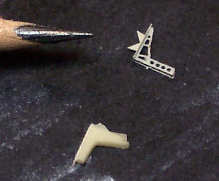 |
|||||||||||||||||||||||||||||||
| The side armor belt extended forward adjacent to the anchor handling area, this was replicated using the RC Cammet self adhesive tape for a sharp and crisp effect. | 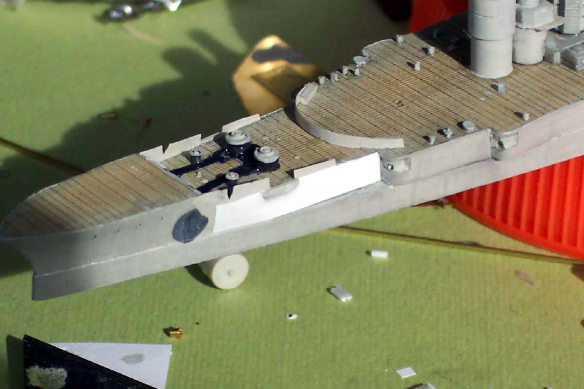 |
|||||||||||||||||||||||||||||||
| Alongside the breakwater, vertically beside the fwd and aft bridge structure there were required large cable reels of un-usual proportions compared to European/US types. I made the drums and ends by placing a heated smooth knife blade to styrene rod and allowing to cool before removing. These items then had their support legs added using scrap handrail parts folded into a triangle; both easy and effective in a small scale. | 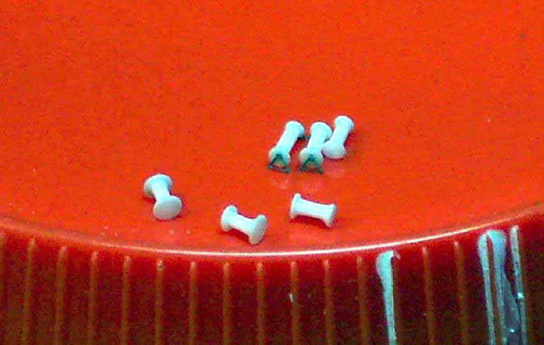 |
|||||||||||||||||||||||||||||||
 |
||||||||||||||||||||||||||||||||
| Having painted the hull and done some preliminary weathering I applied the underwater with bootop trimline this was effected by first applying some white RC Cammett tape and then covering with a strip of narrower red. The edge on the underside of the hull then had runny CA applied so as to prevent any subsequent slippage or distortion. | 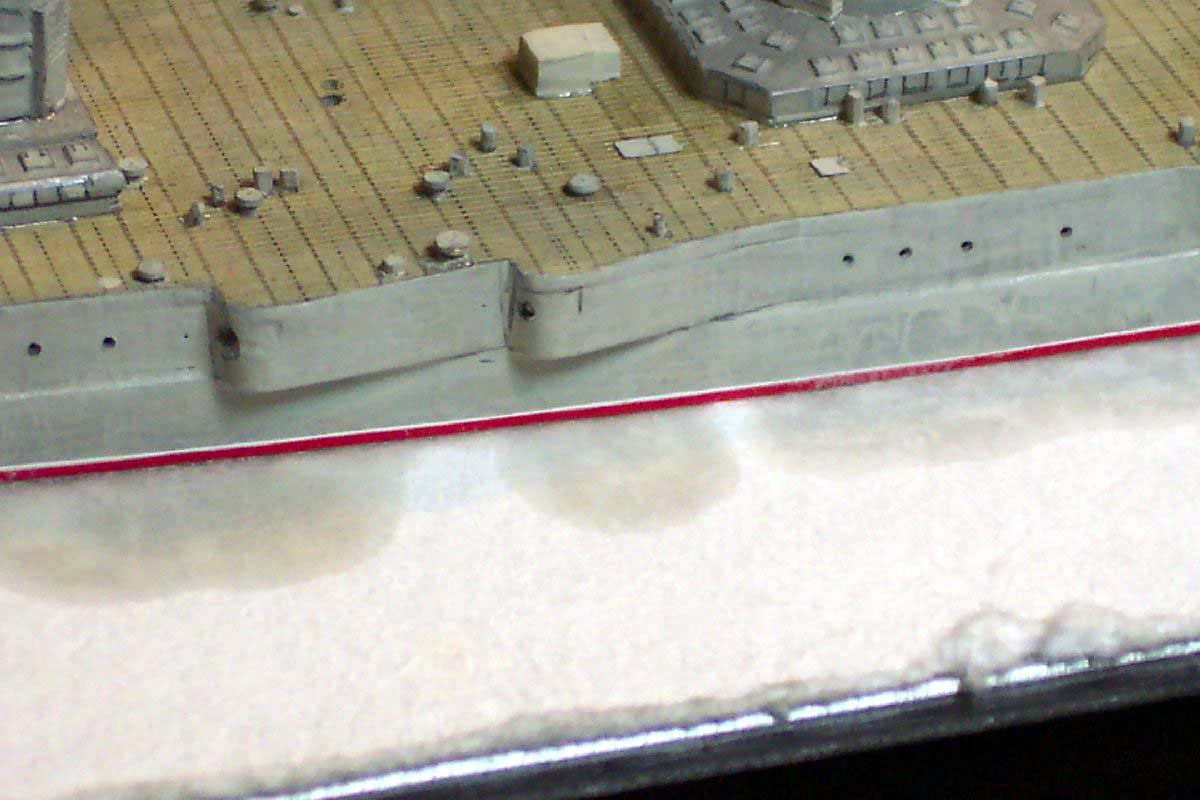 |
|||||||||||||||||||||||||||||||
| I next turned my attention to the forward bridge tower. This on the original ship was built up of numerous decks, with no splinter shields, the open railings were covered with canvas dodgers and window frames placed on top of .(or suspended from the overhead deck?) The kits platform outlines looked good- they were albeit too thick and the window/railing section was cast as a solid lump with windows merely indented far too small. I really had to replicate this area in the same manner as the real thing, so ground off all surplus resin with a motor tool, applied railing and topped off with PE window frames these came from a special fret, more about that later. The second deck level was then placed on top of this delicate structure and the process repeated. The railings were infilled with white glue to simulate the canvas covering. | ||||||||||||||||||||||||||||||||
|
||||||||||||||||||||||||||||||||
| The kit's fwd funnel base was incorrectly proportioned, it did not allow the placement of the first level of stairs... the shaded area shows the area that had to be cut away. | 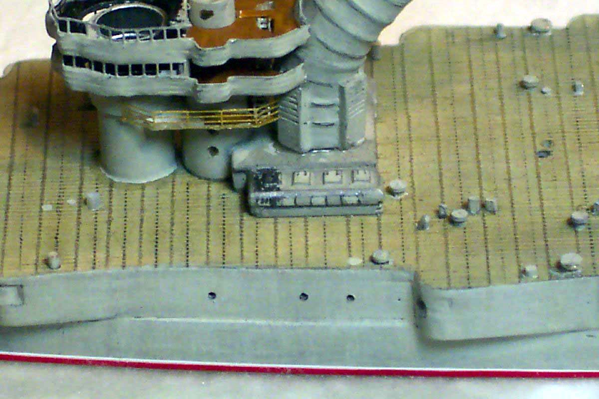 |
|||||||||||||||||||||||||||||||
| As all stairs between the bridge levels are visible from certain angles cutouts had to be made and the twin sets of stairs inserted at every deck level, this required some creative deck carving and adjustment accomplished by the judicious use of white glue and slips of paper. | 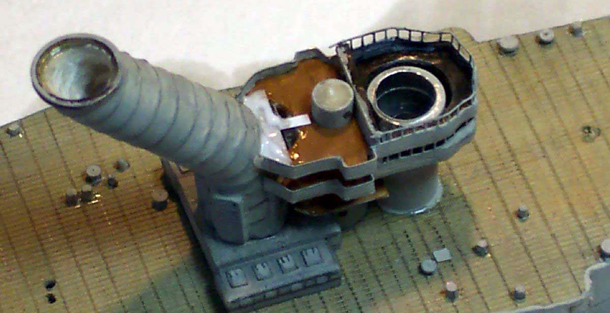 |
|||||||||||||||||||||||||||||||
| The next bridge deck level up required the addition of MG platforms, these were made after the handrail had formed the outline thereof by infilling the apertures thereby formed with thinned white glue, hence ensuring no excess thickness. | 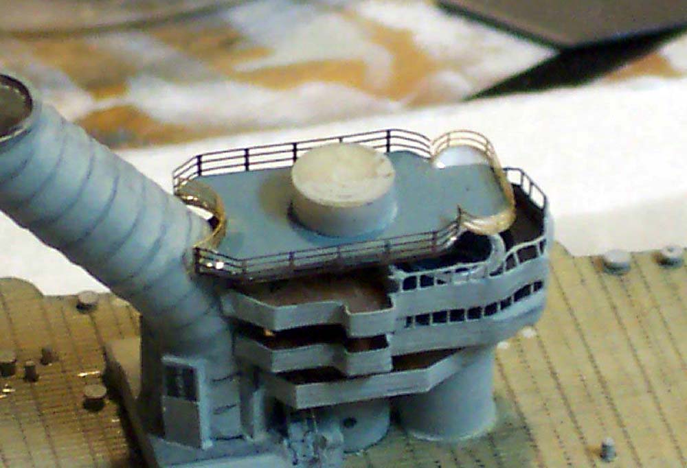 |
|||||||||||||||||||||||||||||||
| The upper (with windows) bridge level had a roof of canvas. This I made using thinned white glue, however so as to prevent it from sagging and to give the meniscus something to grab I installed some paper supports and then backfilled with the glue. | 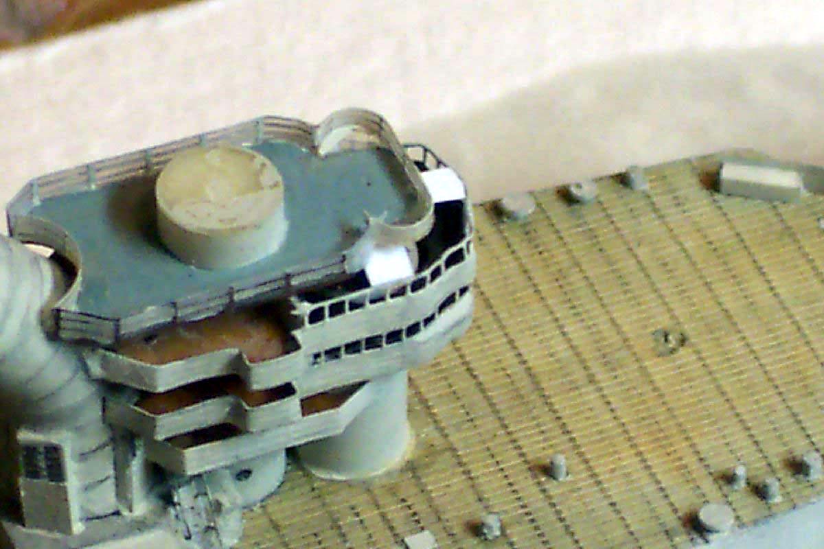 |
|||||||||||||||||||||||||||||||
 |
||||||||||||||||||||||||||||||||
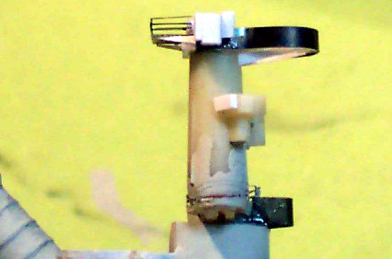
| The upper tapered bridge tower from the kit was very good and was used but supplemented with various small styrene additions. | ||||||||||||||||||||||||||||||||
| I needed to make a correctly shaped upper platform, the thereof 'wall' was made of thin brass ( PE scrap), the wall being painted on the inside first, then the deck was made by infilling the hole with white glue. When dry it becomes transparent , so therefore the underside of the 'floor' was painted, hence giving a perfect color demarcation twixt deck and wall. The under platform braces were made using triangular pieces of paper. | 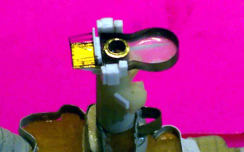 |
|||||||||||||||||||||||||||||||
 |
||||||||||||||||||||||||||||||||
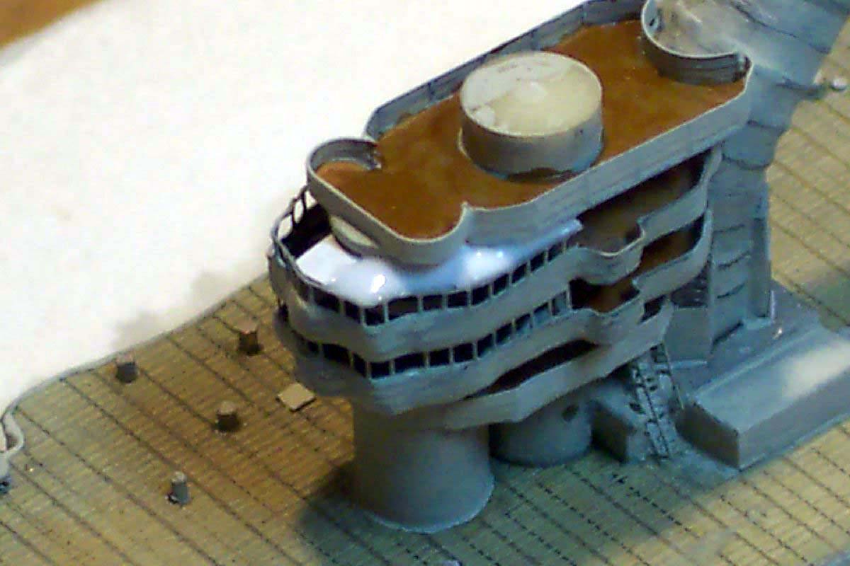
| Paper was again used for the end of platform/funnel joint sheeting, this required a few tries to get right, the photo shows the first (undersized!) template. | 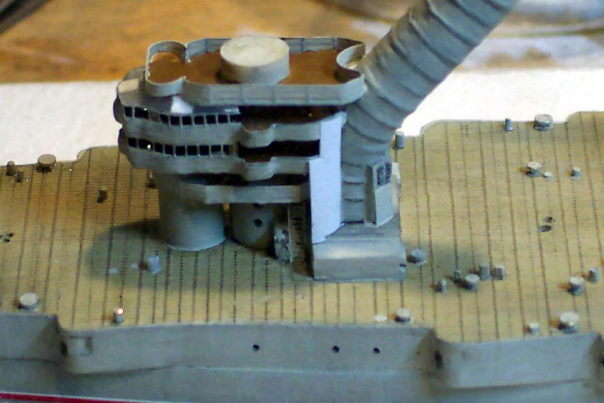 |
|||||||||||||||||||||||||||||||
| Paper was used again for the 'false wall' alongside the lower conning tower, with the stair aperture within. The funnel base inspection hatches were made of brass PE scrap, these were removed and re-applied after I had seen this photo! | 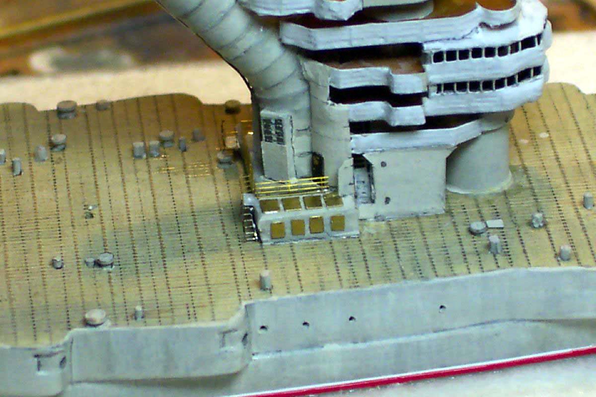 |
|||||||||||||||||||||||||||||||
| The aft superstructure was constructed partly from kit parts and new deck shapes cut of styrene sheet, as the kit parts did not match any of my drawings or photos. The main mast and crane apertures were drilled through the different levels in situ whilst checking for square. The holes were drilled somewhat oversize to allow for final setting up of verticals, the holes being back filled with white glue. | 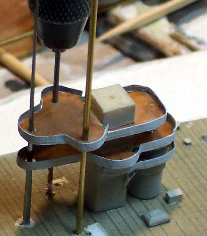 |
|||||||||||||||||||||||||||||||
| The entire structure again has prominent external stairs with intermediate platforms, these were tricky to locate and make work feasibly in a prototypical manner, due in the main to their minute size and fragility. | 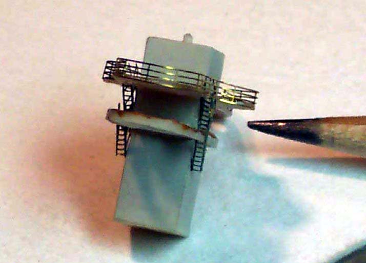 |
|||||||||||||||||||||||||||||||
| The crane leg bases were made of alloy tubing , the slightly convex tops being made with 3 layers of white glue. I find the self levelling properties of this material to be immensely useful in 1/700 model making. | 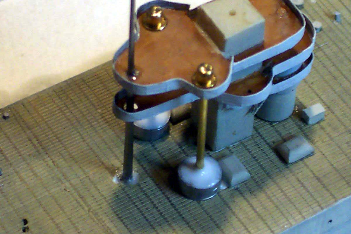 |
|||||||||||||||||||||||||||||||
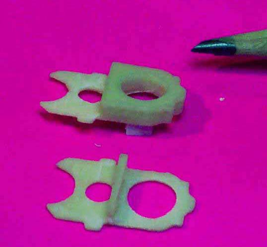
| The main weakness with HP kits sadly is the total lack of any Photoetch parts, even when major components would lend themselves perfectly to this medium. The main stumbling block in this build would have been the huge distinctive girder cranes. These were supplied as a resin casting, which were broadly the right outline shape but alas a solid chunk of resin! | 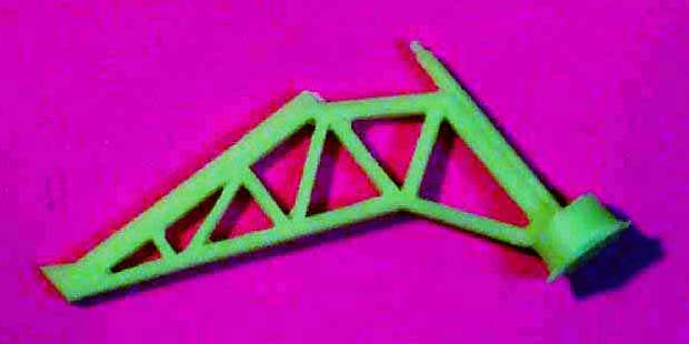 |
|||||||||||||||||||||||||||||||
| I attempted various methods to surmount this problem; I
made a jig and attempted to build the jibs of evergreen strip material
whilst possible I was unable to achieve two , never mind four (!) jibs
that were absolutely identical- exact repeatability was the problem. ..
I scaled down the plan and photocopied the outline to paper and styrene sheet, cutting any of these out perfectly and crisply was beyond both my dexterity and patience! |
||||||||||||||||||||||||||||||||
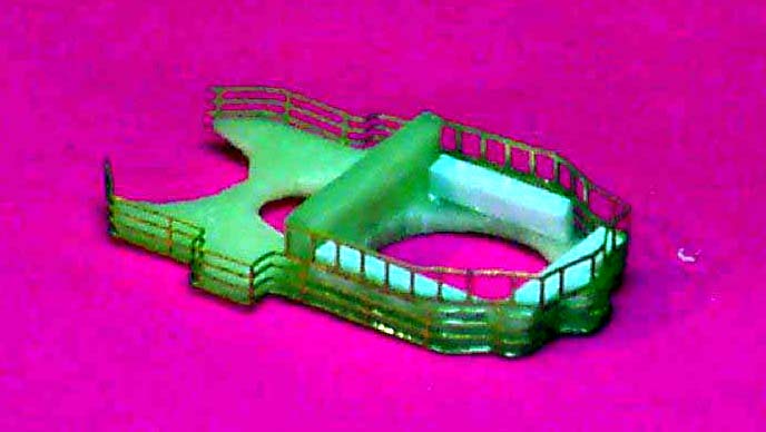
| To the rescue came Peter Hall ( the designer of all WEM PE). I commissioned him to design a custom PE fret to contain those vexed cranes, bridge windows, machine guns etc. , some railing ladders and as a bonus some crane jibs for the Pariziah Comuna, for my next Gangut class ship project. | 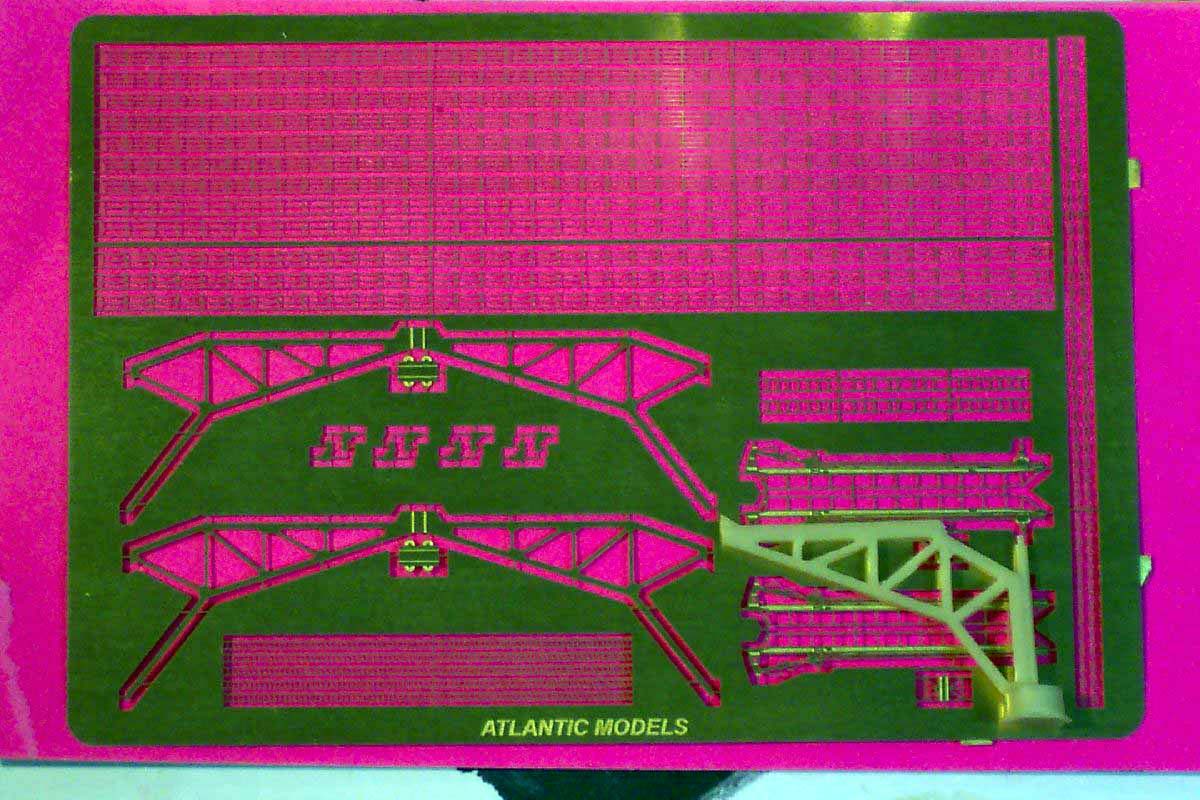 |
|||||||||||||||||||||||||||||||
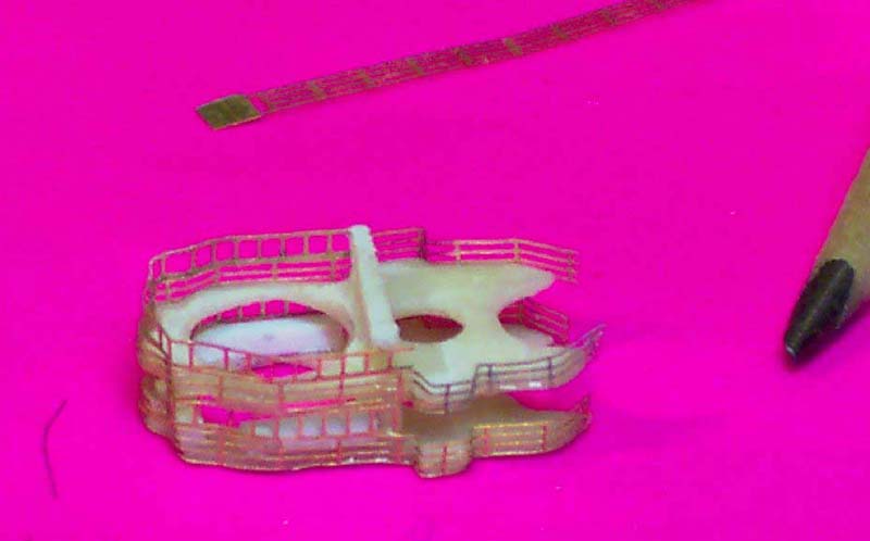
| This solved the repeatability problem in one fell swoop! I bent up the first set of cranes and was delighted. After viewing from all angles and re-consulting yet more photos I came to the conclusion that they now appeared to lack substance and longitudinal profile depth. I circumvented this issue by gluing another set of jibs on the inside of the assembled crane very slightly offset. They were supported apart using small strips of evergreen styrene. | 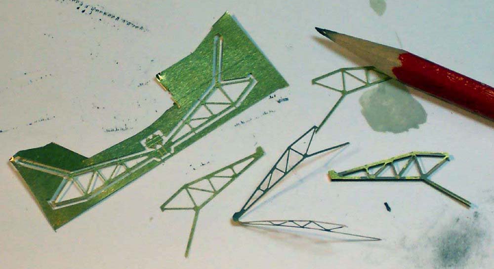 |
|||||||||||||||||||||||||||||||
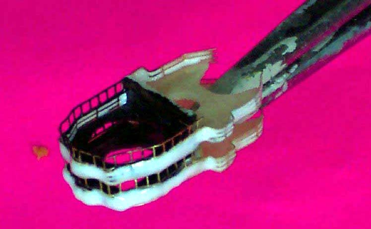
| This allowed me to create a visible line when brushed with a pencil, giving the impression of girder depth rather than a PE blade. | 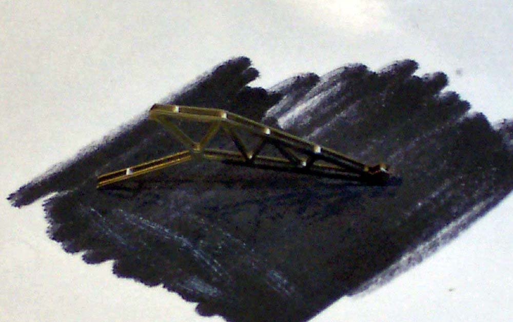 |
|||||||||||||||||||||||||||||||
| For a battleship she carried a decidedly sparse fit of boats which were deployed from cradles on deck and raised boat gantries. The kit supplied boats were actually quite usable, however the boat gantry parts were far too simplistic for my liking , despite their being virtually almost invisible I chose to construct four replacements from pieces of PE from a variety of sources to approximate the correct outline and girder pattern of the original ship; the photo shows the effort in my view to be to be worthwhile! | |
|||||||||||||||||||||||||||||||
| The remaining construction was straightforward, with various details being added in an unremarkable manner, the exception being the huge aerial and halyard spreaders on both masts, these needing to be thin, yet strong enough to resist the cumulative tension of even sprue rigging posing the only true problem. I solved the dilemma by making the yards of the spring steel bristles from a stainless steel wire brush, these resisted all movement much more effectively than brass or nickel silver ever could. | ||||||||||||||||||||||||||||||||
| The project was just starting to become fun with the end at last coming
into sight.... when I discovered a new photo; this showed the crane masts
to be square rather than round. I loathe finding a near catastrophe a long
way into a build yet I fall into these holes with most of my models!
The problem was solved by gluing styrene strips to the crane masts to form a square |
 |
|||||||||||||||||||||||||||||||
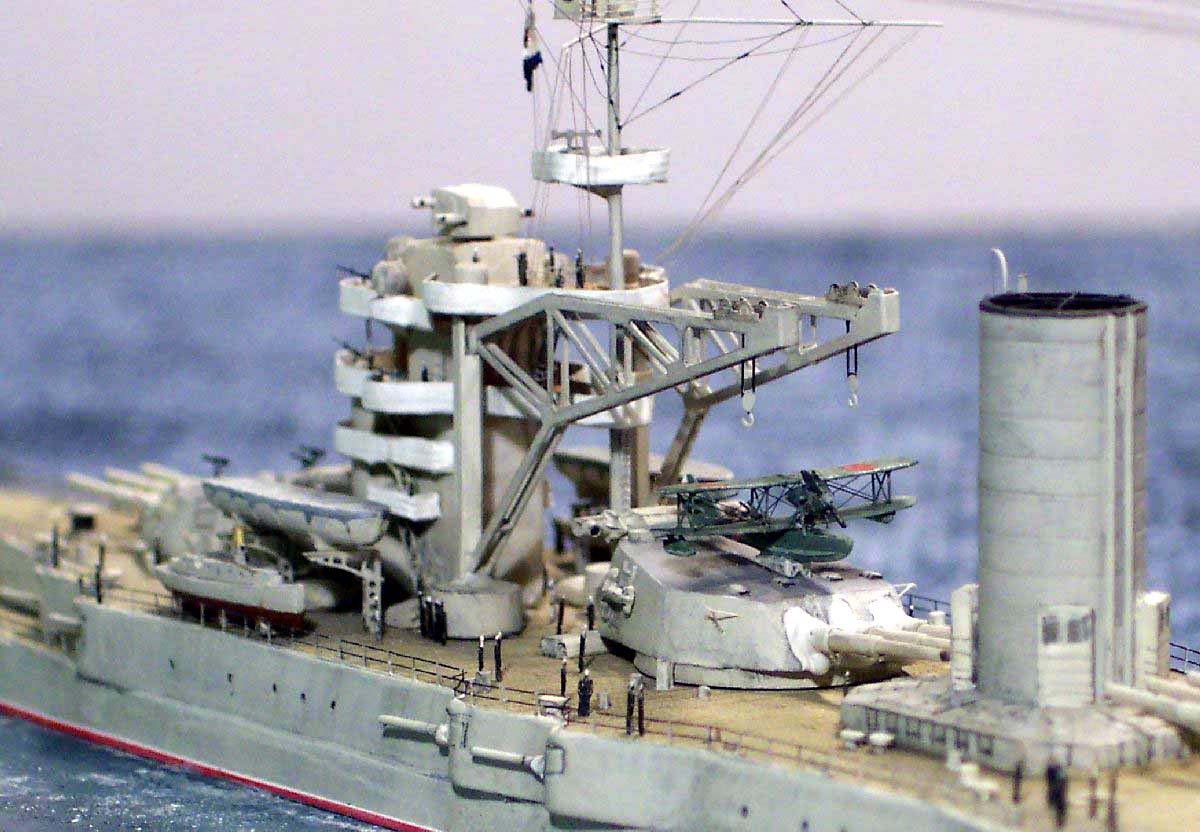
| The ship carried a float plane on turret 3 at various times of her career-- some photos show her without ; then again there are many photos with the KOR-1 perched atop the turret -making the ships side profile even more outrageous to the eye! | 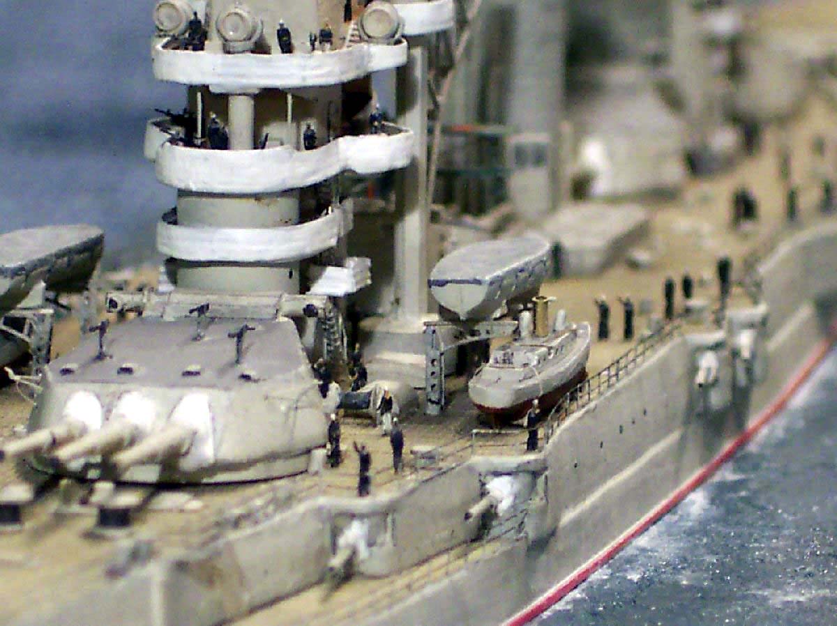 |
|||||||||||||||||||||||||||||||
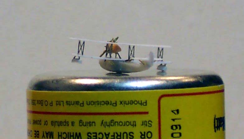
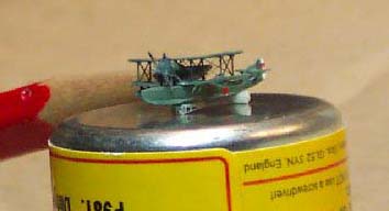
| Although there is no aircraft supplied with the kit I decided it would be an interesting project to scratch build one. I carved the fuselage from a piece of scrap resin casting block . The wings were made of paper infused with CA. I drilled out both cockpits, atop of which perched the engine on a strut assembly. I made the engine cowling from a cocktail stick dipped into CA to harden it, merely adding a more rounded profile to the existing point. Pieces of cut down handrail were used for the struts under the tail plane and main wings and also to make the twin barrels of the aft cockpit machine guns. I utilized the interplane struts from a GMM PE fret this ensured absolute symmetry. When painted I applied some Soviet star decals from a Pitroad set, alas these had white centres, so I hand painted the inside of the stars in solid red. I rigged the aircraft with stretched sprue. | 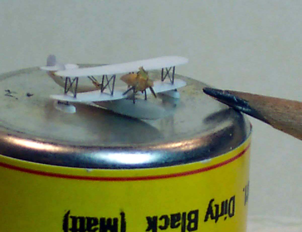 |
|||||||||||||||||||||||||||||||
 |
||||||||||||||||||||||||||||||||
 |
||||||||||||||||||||||||||||||||
| All the deck edge railings used were GMM Gold plus Superfine, colored with a permanent marker with the individual stanchions picked out in hull color, the black for and aft cables being very lightly dry brushed to tone them down. | 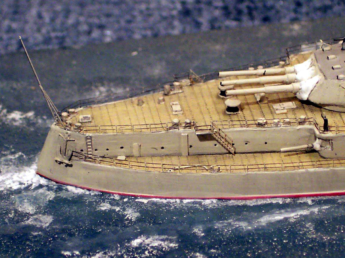 |
|||||||||||||||||||||||||||||||
| Some of the upper levels and the bridge structure were furnished with more robust items from the Peter Hall fret. The figures are GMM, stairs and anchors are WEM, the inter war naval ensign is from the venerable GMM flag decal set. | 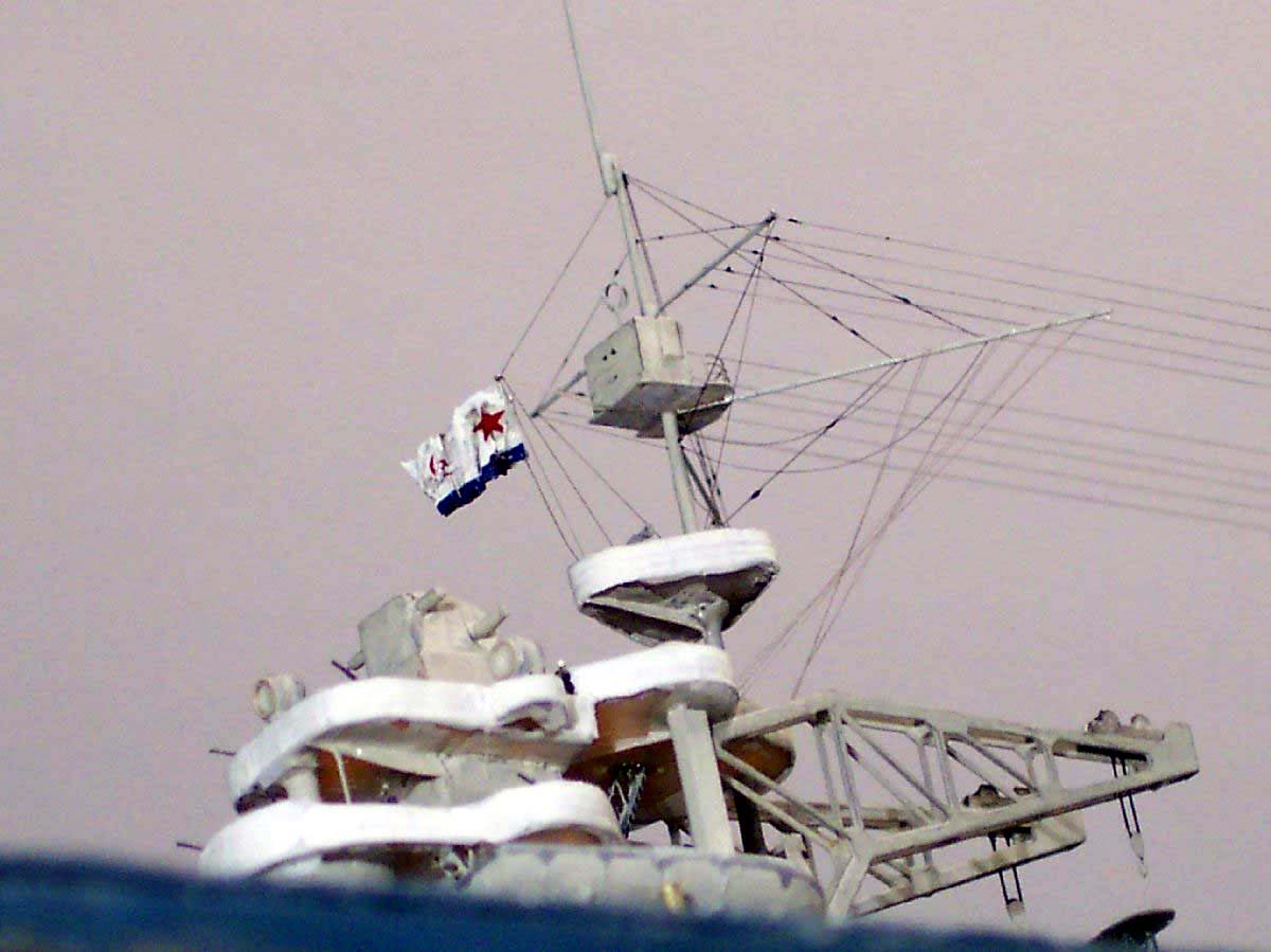 |
|||||||||||||||||||||||||||||||
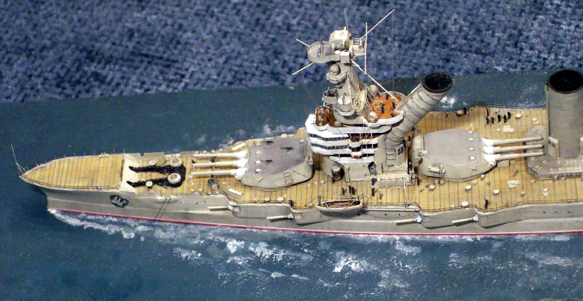
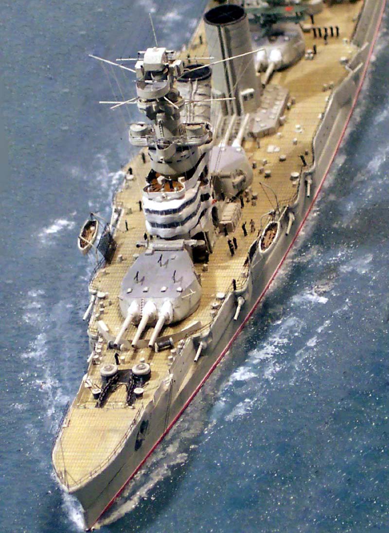
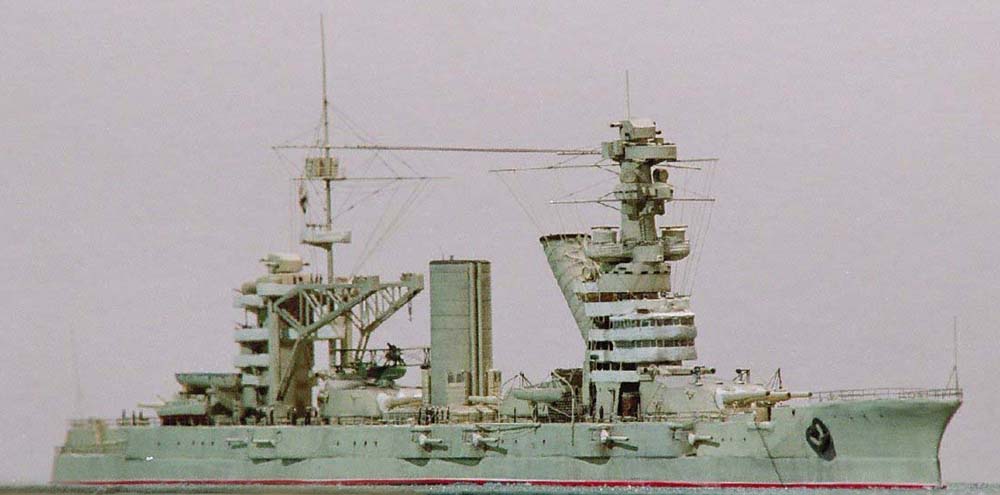
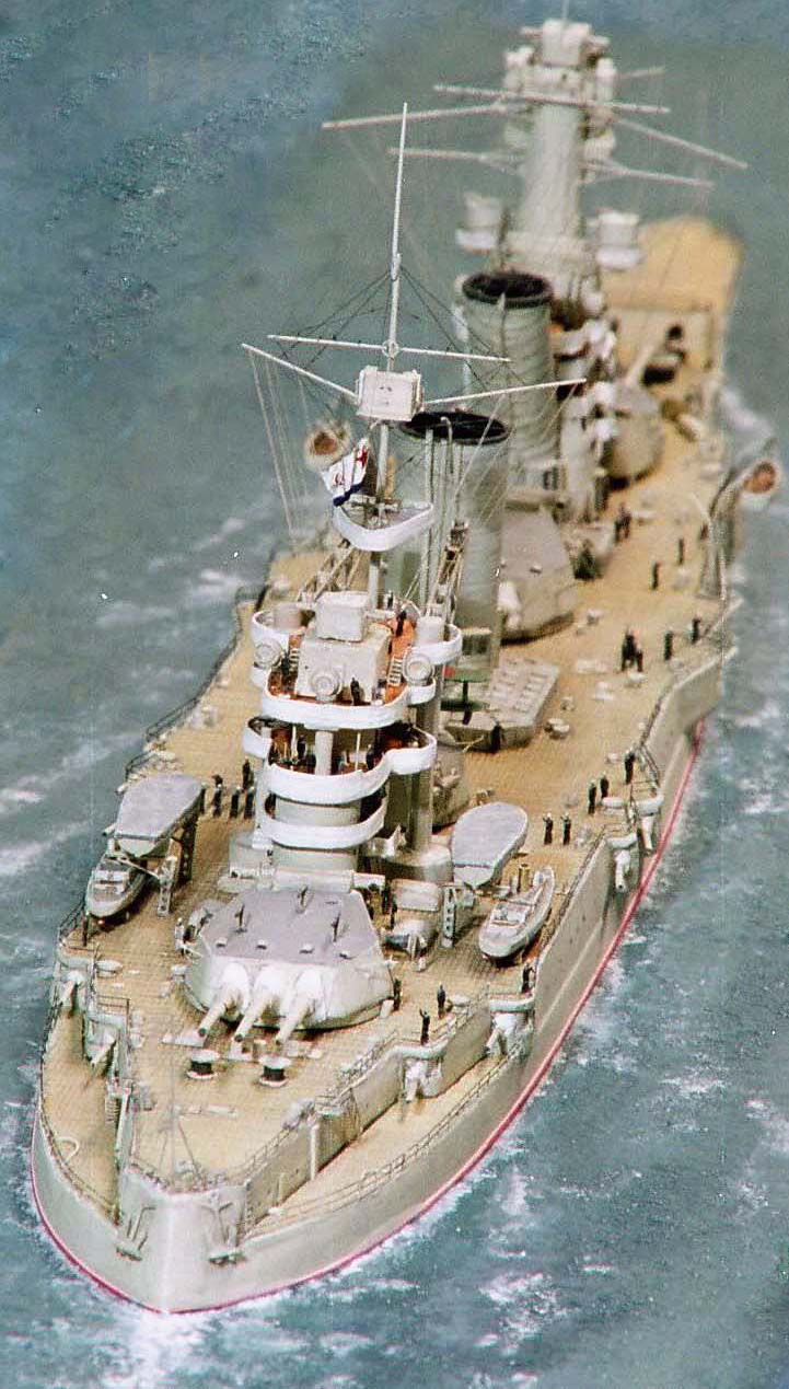
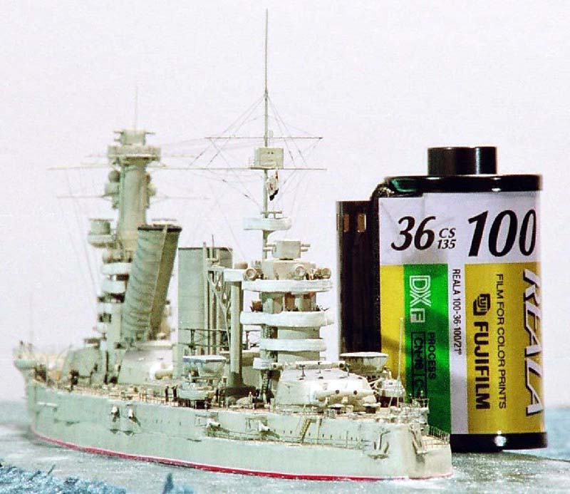
| Being a long hulled ship I mounted her on my usual GMM stainless steel plate to prevent any warpage of the hull in the future. Most photos of Oktabrina show her either at anchor or proceeding slow ahead, I have yet to locate a picture of her at speed so I chose to portray her trickling ahead at 8 -10 knots or so. I rigged the whole ship using black stretched sprue for the standing rigging and WT antennas, the ten(!) longitudinal items being a particular challenge. So as not to overpower the visual effect ship the signal halyards were made of light brown stretched sprue the overall effect is quite pleasing. | ||||||||||||||||||||||||||||||||
| I also used stretched sprue for making the top funnel grates as well
as the handrails on the fwd funnel .Sprue was used for the straps securing
the sea boats that are slung in davits. I have found the GMM stainless
steel etched pulley sets can be cut into a very useful material for making
robust but delicate ensign staffs.
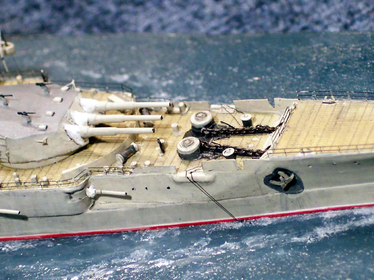
The Anchor cables had check chains added of Black sprue, the mine cutting gear cables were added of sprue also. |
 |
|||||||||||||||||||||||||||||||
| The paint used all over was Humbrol 28 but washed down in various shades of enamel and watercolor. Lino decks were painted using WEM Colourcoats Corticene washed with light gray to knock down the intensity. Canvas dodgers were painted using Revell white this is a creamier white than Humbrol and not as glaring on a finished model. | ||||||||||||||||||||||||||||||||
|
||||||||||||||||||||||||||||||||
| I have to extend my thanks to all my virtual and tangible friends via the interenet without who I would have had many a headache without answers! | ||||||||||||||||||||||||||||||||
Principal Bibliography:
In conclusion the HP kit is fundamentally about right- giving a fair
springboard start over scratch building a model of this ship alas the lack
of PE and some simplification is, sadly, however not reflected in the relatively
very high price.
Should anyone wishing to attempting a model of Oktabrina/Paraziah Komuna want to make me a sporting offer for some the numerous surplus crane PE frets( due to minimum order at the etchers!) --it may help me recover some of my costs and make the commission of a future custom ship fret more tempting please contact me!! |
||||||||||||||||||||||||||||||||
|
|
||||||||||||||||||||||||||||||||